Clay tiles can be put on a wide range of substructures. It would not be possible to illustrate every combination of roof structure and tile fixing method. Nevertheless, the range of examples given below should meet the needs of most new and replacement roofs.
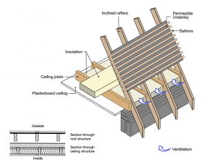
Roof with insulation at ceiling with impermeable underlay
This is a traditional roof detail with a ventilated roof space and horizontal ceiling. Ventilation should be provided into the roof space in accordance with Approved Document C of the English building regulations (and its equivalents in Scotland, Northern Ireland and Wales), and British Standard BS 5250.

Roof with insulation at ceiling with permeable underlay
This roof detail shows a horizontal ceiling and using a vapour permeable underlay without roof space ventilation.
Ventilation should be provided in accordance with Approved Document C of the English building regulations (and its equivalents in Scotland, Northern Ireland and Wales), and British Standard BS 5250.
Low and high level ventilation should be provide to the batten cavity.
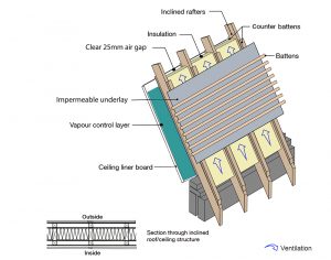
Roof structure – insulation at rafter with impermeable underlay
This detail shows a sloping ceiling and uses a non-vapour permeable underlay and is suitable where there is a room in the roof space. Insulation is fitted between the rafters.
It is recommended that a clear ventilated air gap no less than 25mm must be positively ventilated in accordance with Approved Document C of the English building regulations (and its national equivalents in Scotland, Northern Ireland and Wales) between the underlay and the insulation.
To allow for drape, counter battens of 38mm to 50mm are recommended
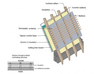
Roof structure – insulation at rafter with permeable underlay
This detail shows a sloping ceiling and uses a vapour permeable underlay without roof space ventilation and is suitable where there is a room in the roof space. Insulation is fitted between the rafters.
A vapour control layer is fitted to the warm side of the insulation in accordance with BS 5250.
An alternate version of this design is that it incorporates an additional layer of insulation below the rafters above the ceiling.
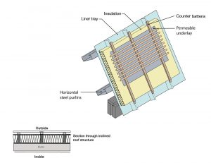
Roof Structure – insulated liner tray system
This detail shows the use of a metal liner tray system fixed to horizontal steel purlins. Rigid insulation is positioned between the upstands of the liner tray.
Permeable underlay is laid over the upstands and counterbattens are secured to the upstands using proprietary fixings as recommended by the liner tray manufacturer. Tile battens are then nailed to the counterbattens in the usual way.
In this construction, the metal liner tray acts as the vapour control layer so care must be taken to prevent any unsealed penetrations.
Where a suspended ceiling system is used (not shown), advice should be sought from the liner manufacturer.
Roof Structure – Pre-formed insulated liner tray system
This detail shows the use of a metal pre-formed liner tray system with insulation ‘sandwiched’ between lower and upper metal panels. The system is fixed to horizontal steel purlins. Tile battens are secured directly to the panel using proprietary fixings as recommended by the liner tray manufacturer
A suspended ceiling system is used (not shown).
(Advice should be sought from the liner tray manufacturer)
