Box gutter eaves
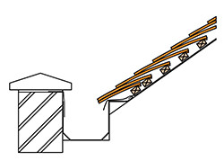
Fix continuous timber tilt batten at eaves to provide support for metal flashing and eaves course of tiles.
Cover metal gutter lining up overthe tilt batten and extend under the eave course by minimum 150 to 200mm .
Lap roof underlay over metal welt.
Note: An over fascia ventilation strip could be positioned on top of the tilt fillet to provide low level ventilation, but air flow may be restricted, depending upon the height of the wall.
The designer must also be satisfied that the gutter will not become blocked with debris or by freezing and cause flooding into the roof space through the ventilator. If either of these points are of concern then ventilation tiles should be provided clear of the wall and gutter instead.
Bonding gutter with metal lining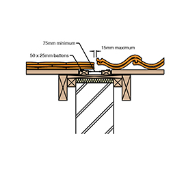
Ensure that gutter board is wide enough to provide full support for ends of tile battens, tilt battens and the valley lining. Pack the void between the board and top of party wall with quilt insulation.
Turn underlay over timber tilt battens either side of bonding gutter. Use tiles and tile-and-a-half tiles to form a gap no greater than 15mm between plain tiles and adjacent roof covering.
Pipe flashing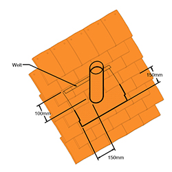
This detail shows a standard metal flashing for use with a 100mm diameter pipe.
The metal flashing should extend a minimum of 150mm below and to each side of the pipe and at least 100mm under the tiles above the pipe, ending in a welt.
The flashing should extend at least 150mm up the pipe, measured at the back of the pipe.
The flashing can be turned into the pipe, as shown here. Alternatively, a pipe collar can be fitted to weather the joint between flashing and pipe.
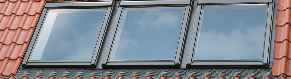
Roof window flashings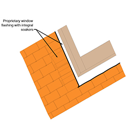
Roof windows can be supplied with the appropriate pre-formed flashing suitable for use with plain tiles.
At the top edge the flashing forms a top or ‘back’ gutter.
At the bottom edge the flashing forms a cover flashing over the course of tiles below the window.
At the sides of the window integral soakers interleave with the tile courses. (See roof window manufacturers details for specific installation details)
Safety hook fixings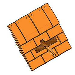
Penetrations through the tiling such as pipes or safety hooks should be weatherered using a suitable metal flashing.
The flashing should be turned over the top of the tiles.
Metal saddle to ridge junction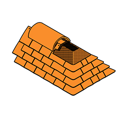
Suitable metal saddles should be fitted at junctions such as between ridge and hip, ridge and valley, ridge and abutment and at the top of two valleys.
This particular drawing shows a typical saddle between ridge and hips.
The saddle should extend at least 100mm over the top courses of tiles.
A special hip stop end ridge tile should be fixed over the metal saddle – not shown for clarity.